
COMPUTERISED TILTING FLUME APPARATUS
Project Information
- Category: MECHANICAL ENGINEERING
- Sub Category: Process Control Trainer
- Model Number: PM-P1050
- Category: MECHANICAL ENGINEERING
Description
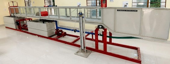
This apparatus consists of a flow channel fabricated from transparent toughened glass with stainless-steel windows on either side. The equipment is designed to study various flow phenomena in an open channel using different types of blocks, gates, weirs and other accessories. The transparent channel section allows observation of flow patterns and photographs to be taken. The glass panels are sealed with a stainless-steel bed. The channel is floor mounted and provided with an instrument rail along the complete working length. A pointer gauge is provided to measure the depth of flow and can be moved along the rail. An inlet tank with a stilling and smoothing device is provided for obtaining a smooth water profile. The discharge side is fitted with an adjustable-height gate to maintain operating water levels. The flume is suitable for studying and calculating the slope of the channel. A computerised tilting flume apparatus is an advanced hydraulic laboratory system used to study open-channel water flow, wave mechanics, and sediment transport. Key features typically include a transparent test channel, an electronic motorized tilting mechanism, and digital data acquisition software.
- Core Components and Design
Channel dimensions: Standard working lengths range from 5 meters, widths around 300 mm, and depths around 300 mm. - Structure materials: Built with a rigid mild steel or stainless-steel framework and clear Perspex or toughened glass side walls for full visibility.
- Water circulation: Includes a stainless-steel sump tank, a quiet re-circulating water pump, and flow regulation control valves.
- Computerized & Automated Features
- Digital control: Integrated touchscreens or computer interfaces to manage pump speed and slope adjustments accurately.
- Sensors and meters: Equipped with electronic pressure sensors, digital flow meters, and automated level gauges to record data in real time.
- Data logging: Software packages that plot flow profiles, discharge rates, and gradient slopes without manual calculations.
- Common Laboratory Applications
- Flow visualization: Observing subcritical, supercritical, and uniform/non-uniform flow patterns.
- Hydraulic structures: Testing the behavior of broad-crested weirs, sluice gates, and spillways.
- Wave and energy studies: Analyzing specific energy, hydraulic jumps, and boundary
EXPERIMENTATION
- To observe the Hydraulic Jump phenomenon.
- Study of velocity distribution in an open channel and determination of correction factor.
- Other experiments can be performed using additional accessories.
UTILITIES REQUIRED
- Water Supply: Initial fill.
- Laboratory Drain.
- Electricity Supply: 220 VAC, 50 Hz, 2 kW maximum.
MODELS / ACCESSORIES SUPPLIED A) Weirs
- Sharp Crested Weir (Crest Length: 200 mm).
- Broad Crested Weir.
- Ogee Weir or Spillway.
- Venturi Flume.
ADDITIONAL FEATURES
- Sump tank of suitable capacity.
- Tanks fabricated from stainless steel.
- English instruction manual containing experimental procedures, block diagram, etc.
- Complete setup mounted on a rigid, well-designed structure.
- Structure finished with industrial PU paint.
Technical Details
| PARAMETER | SPECIFICATION |
| Flow Channel Material | Toughened Glass and Stainless Steel. |
| Flume Width | 300 mm. |
| Flume Depth | 300 mm. |
| Flume Length | 5 m. |
| Test Section | Normally 5 m; test section length can be provided as required. |
| Test Section Width | 300 mm / 400 mm options. |
| Total Length | 5 m test section with approximately 4 m working length. |
| Windows | Transparent windows on either side of the test section, approximately 400 mm long and 400 mm wide. |
| Wind Section | Total length approximately 4000 mm, with width corresponding to the selected test section. |
| Water Circulation | Centrifugal pump of suitable capacity. |
| Flow Regulation | Valve-controlled flow regulation. |
| Pointer Gauge | Provided for measuring water depth. |
| Rail | Instrument rail provided along the complete working length for movement of the pointer gauge. |
| Sump Tank | Suitable capacity. |
| Tank Capacity | Approximately 400 litres. |
| Pump | 2 HP centrifugal monoblock pump. |
| Gates | Sliding gates provided at upstream and downstream sides. |
| Orifice Meter | Provided with manometer for measuring discharge. |
| Orifice Dimensions | Inlet 50 mm / Throat 25 mm respectively. |
| Mass Flow Rate | Can be calculated using the formula: ṁ = ρCQ. |
| Space Required | Approximately 7 m length × 1.5 m width. |
Catalouge: View Download
Clients
Making Quality Laboratories Affordable & Accessible
We specialize in delivering comprehensive 360-degree laboratory solutions tailored to your needs. Our services encompass lab design, expert consultation, supply of high-quality equipment, on-site installation, and hands-on training.
With a proven track record, we have successfully established over 1,800 laboratories across 1,000+ institutions throughout India.
Our esteemed clientele includes organizations such as DRDO, NITs, Polytechnic Institutes, Industrial Training Institutes, Kendriya Vidyalayas, Jawahar Navodaya Vidyalayas (JNVs) ONGC, and many more.